
Features:
WIFI Smart fan coil thermostat is designed to on/off control the fans and valves in air conditioner applications via comparison of the room temperature and setting temp. as reaching the aim of comfort and saving energy.
Appearance:
1. 86mm hidden box and European 60mm round box is suitable.
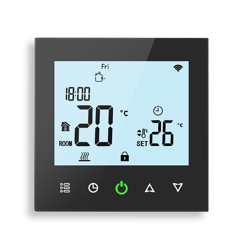
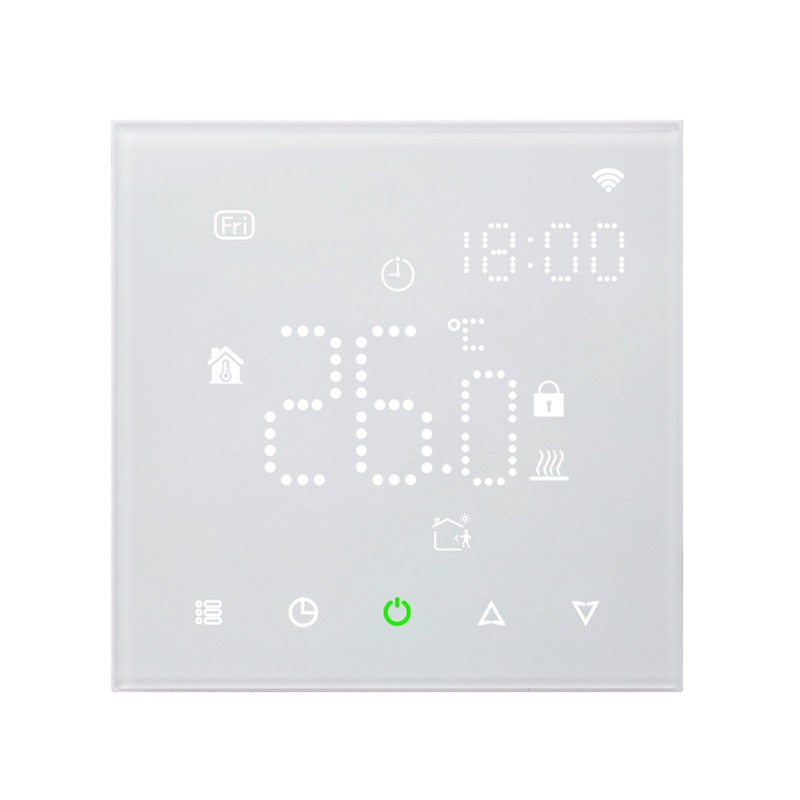
2. White, black or mix-color housing creates your colorful life.
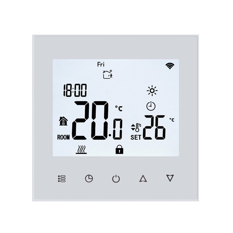
3. White backlight protects your eyes.
4. Touch buttons to make simple operations.
Function:
1. Powerful functions are available such as WIFI, BLE, ZigBee, Modbus, etc.
2. 0.5℃ Accuracy keeps the temperature within the level you set.
3. Clock memory when power is off.
4. 5+2 six periods programmable maximize comfort and economy.
5. Creat thermostat group to centrally control.
6. Integrated with Amazon Echo, Google Home, Tmall Genie.
7. Support device sharing with your family or friends.
8. All setting languages synchronize your time zone, address, and language.
9. No limit to adding thermostats in APP.
Technical Data:
Power Supply: 95~240VAC, 50~60Hz
Fan Relay Amps Resistance: 5A; Inductive: 3A
Valve Relay Amps Resistance: 3A; Inductive: 1A
Sensor: NTC 3950, 10K
Accuracy: ±0.5℃
Set Temp. Range: 5-35℃
Display Temp. Range: 5~99℃
Ambient Temp.: 0-45℃
Ambient Humidity: 5~95% RH (Non-Condensing)
Storage Temp.: -5~45℃
Power Consumption: <1.5W
Timing Error: <1%
Shell Material: PC+ABS (Fireproof)
Installation Box: 86*86mm Square or European 60mm Round Box
Protection Level: IP20
Buttons: Capacitive Touch Buttons
MODEL SELECT
√Types | 2-Pipe | 4-Pipe | Programmability | WiFi Control | |
SS211F | √ | √ | |||
SS211FV | √ | √ | |||
SS211F-WF | √ | √ | |||
SS211FV-WF | √ | √ |
|
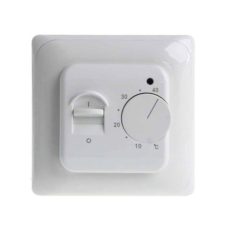
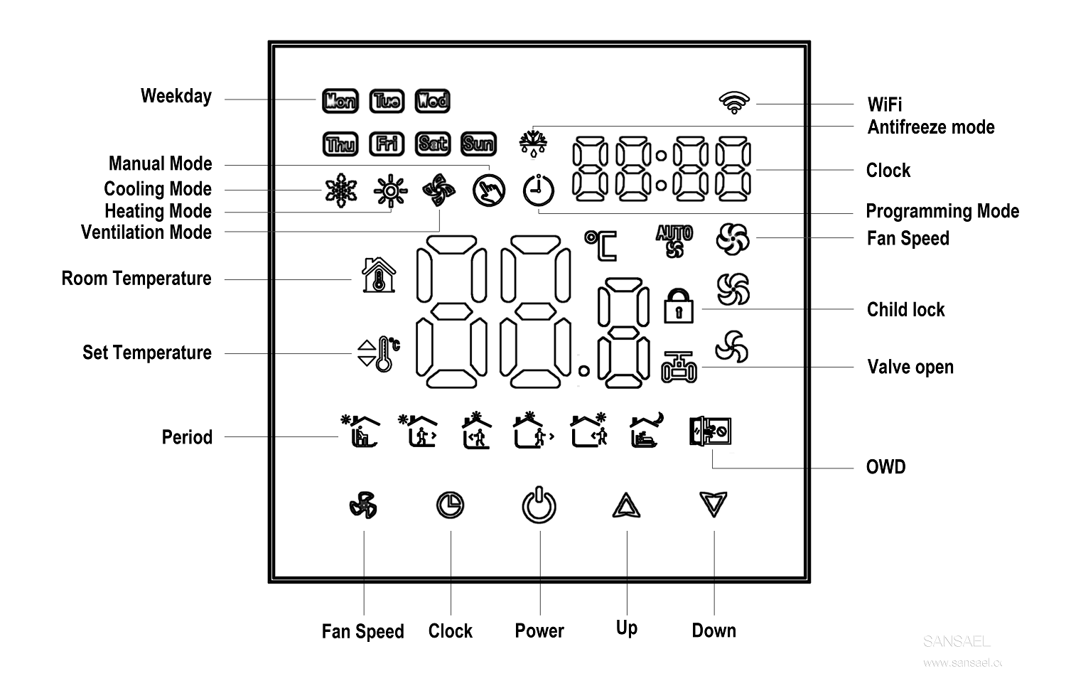
PRODUCT DISPLAY
INSTALLATION
Your thermostat is suitable for installation within a standard 86mmpattress box or European 60mm pattress box.
Step 1. Keep power off. See Fig 1.
Step 2. Remove the mounting plate by rotating the LCD part. See Fig 2.

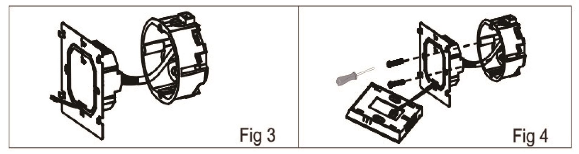
Step 3. Connect the power supply, load into the appropriate terminals(see "Wiring your thermostat" for details and Fig 3).
Step 4. Fix the mounting plate into the wall with screws in the box. See Fig 4.
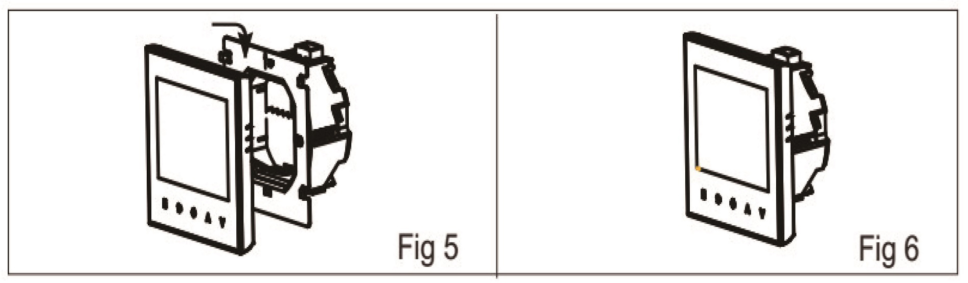
Step 5. Fasten the body of the thermostat and the mounting plate through rotating. See Fig 5.
Step 6.Installation complete. See Fig 6.
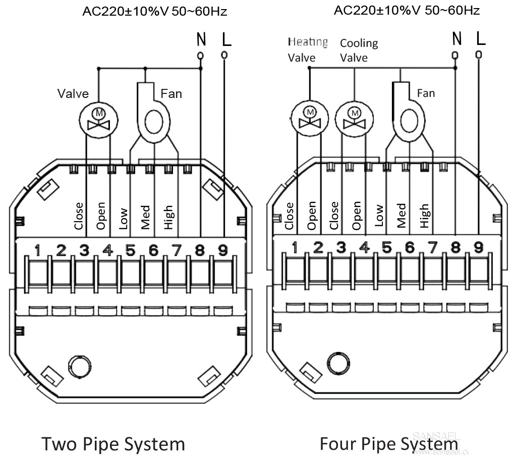
WIRING DIAGRAM


Long Press to Scan QR Code
Scan QR Code